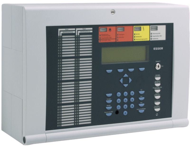
FACP IQ8Control C


Description
The Arduino Ethernet Shield allows an Arduino board to connect to the internet. It is based on the Wiznet W5100 ethernet chip providing a network (IP) stack capable of both TCP and UDP. The Arduino Ethernet Shield supports up to four simultaneous socket connections. Use the Ethernet library to write sketches which connect to the internet via a standard RJ45 Ethernet jack using the shield.
The latest revision of the shield adds a micro-SD card slot, which can be used to store files for serving over the network. It is compatible with the Arduino Uno and Mega (using the Ethernet library). You can access the on-board SD card slot using the SD library which is included in the current Arduino build.
The latest revision of the shield also includes a reset controller, to ensure that the W5100 Ethernet module is properly reset on power-up. Previous revisions of the shield were not compatible with the Mega and need to be manually reset after power-up. The reset button on the shield resets both the W5100 and the Arduino board.
Arduino communicates with both the W5100 and SD card using the SPI bus (through the ICSP header). This is on digital pins 11, 12, and 13 on the Duemilanove and pins 50, 51, and 52 on the Mega. On both boards, pin 10 is used to select the W5100 and pin 4 for the SD card. These pins cannot be used for general i/o. On the Mega, the hardware SS pin, 53, is not used to select either the W5100 or the SD card, but it must be kept as an output or the SPI interface won't work.
The IQ8Control C is an efficient fire alarm control panel for the property supervision of small to mid-sized objects facilitates simultaneous detection, control and alarm signaling both on the analog ring as well as on the spur.


Within the multi-functional IQ8Control C panel, the operation type (powered-loop or non-powered-loop) can be selected via a jumper located on the control panel power supply unit.


Depending on which loop operation type has been selected, the corresponding loop module/modules are required.


Part No.: 808003 Approval: VdS, CNBOP, BOSEC


Features


Max. two micromodules (system supports up to 254 digital loop addresses in total)

Max. two esserbus analog loop modules

Short circuit and open circuit resistant loop operation

Loop installation with I-Y(ST)Y 0.8 mm cable for a maximum length of 3.5 km

Up to 127 esserbus devices (fire detectors and/or manual call points)/detector zones per loop

Up to 32 esserbus transponders per loop/operation of wireless components (see chapter 10)

Operation types TM and PM as per DIN VDE 0833 - 2 to avoid unwanted alarms being triggered

Fire brigade operating panel and alarm transmission unit interface on the peripheral module

Three common relays, freely programmable, monitored, floating for up to 24 V DC/1A (on the peripheral module)

TTY or RS 485, RS 232 interface

Integration in the short circuit and open circuit resistant essernet network with up to 31 fire detection panels depends on transmission rate

Connection to graphical supervisor FlexES Guard/WINMAG via serial essernet interface (SEI)

Operating panel with alphanumerical display

Large display with 8 rows with 40 characters. As follows rated - four rows with 40 characters for the status information (first and last message), and the other four rows with 40 characters are used for system information e.g. “Sounders Off”

Event memory for up to 10,000 events

All System 8000 micromodules are compatible

Printer interface for internal printer

Two batteries with monitoring circuit

Monitored input for external power supply unit

Additional features for powered loop

Max. 2 analog powered loop modules (System supports up to 254 digital loop addresses in total)

BUS powered, synchronously controlled, acoustic alarm signaling devices as per DIN EN 54-3 with alarm tone as per DIN 33404

Up to 48 powered loop base sounders (series 9200) per loop

Up to 32 powered loop IQ8Alarm per loop

Up to 48 IQ8Quad with alarm device per loop